
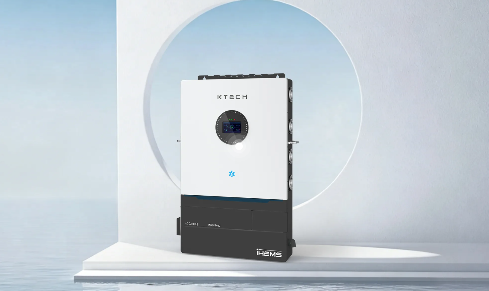
Opening: why commissioning fails, fast
Most projects blow their uptime targets not because of bad hardware but because commissioning skips verification layers. You can spec an off-grid solar system with premium cells and a compliant inverter, and still see chronic trips: mismatched BMS thresholds, inverter handshake errors, or wrong SoC calibrations. Field teams call these “paper-compliant” systems — they pass checklists but not real loads. That gap shows up in disaster-response zones; look at Puerto Rico after Hurricane Maria and you’ll see how commissioning deficits translate to months of lost resilience.
Core failure modes to catch during commissioning
– BMS comms misconfiguration (CAN/RS-485 baud and ID mismatches).
– SoC drift because pre-charge and full-charge voltages weren’t calibrated per cell-group.
– Trip thresholds set to default OEM values that don’t match site ambient derates.
– Inverter/BMS handshake failures during blackstart or islanding transition.
– Inadequate telemetry bandwidth blocking firmware health telemetry during soak tests.
Stepwise commissioning workflow (practical, no fluff)
– Stage 0 — Visual & documentation audit: serials, firmware versions, wiring diagrams, torque on DC lugs.
– Stage 1 — Communications baseline: validate CAN/RS-485, MQTT/Modbus over the site LAN; confirm packet loss <0.1% for 5 minutes.
– Stage 2 — BMS cell balancing and SoC calibration: run controlled charge/discharge cycles to map per-cell voltages and adjust SoC table.
– Stage 3 — Inverter/BMS integration: validate handshake for grid-forming/grid-following modes, confirm anti‑islanding thresholds and reconnection timing.
– Stage 4 — Protection setpoints and relay sequencing: simulate faults, verify coordination with upstream breakers and generator controls.
– Stage 5 — Performance soak: 72-hour dynamic load profile that includes ramp rates, sustained discharge, and PV ramp events; capture logs for analysis.
– Stage 6 — Handover: provide the owner a trimmed log package, firmware baselines, and a repeatable SOP for periodic verification.
Instrumentation, telemetry, and acceptance tests
Use the right probes and sampling rates. High-frequency ripple needs a scope at 10 kHz; steady-state SoC validation can use battery coulomb-counting with daily reconciliation. Acceptance criteria should be numeric: round-trip efficiency ±2% of factory spec, SoC drift <1% after 72 hours, BMS packet loss <0.1%. Build test harnesses that auto-flag anomalies so field techs don’t chase non-deterministic faults.
Common pitfalls and fixes
– Pitfall: relying on factory default protection curves. Fix: profile the site thermal envelope and derate trip thresholds accordingly.
– Pitfall: manual SoC correction without logging. Fix: run a controlled charge/discharge cycle and anchor SoC to measured coulombs.
– Pitfall: ignoring PV/inverter handshake under low irradiance. Fix: simulate low-irradiance transients during soak tests.
– Pitfall: insufficient telemetry retention. Fix: prioritize rolling 30-day logs with exportable CSVs for warranty claims.
Field validation, KPIs, and operational gating
Gate operational handover on measurable KPIs: successful islanding transitions (3 of 3), sustained full-load discharge for the rated duration, and no BMS reboots during PV transient tests. For distributed deployments or remote microgrids, validate remote firmware rollback paths and secure OTA channels. These checks are non-negotiable for any scalable off-grid energy storage rollout where on-site intervention is costly.
Closing synthesis
Commissioning is an engineering loop: detect, quantify, baseline, lock, and document. Treat each step as a test vector that must pass objective thresholds rather than a signed checklist. Operational reliability springs from that discipline, which is exactly the practice firms in resilient power deployments follow, including teams at Ktech.