

Introduction: Define the Envelope, Then the Finish
Start with the building envelope as a system. Aluminum Panel shows up on site because schedules are brutal and margins are thin. On a mid-rise, a crew can set 400–600 m² of cassettes per day, while brick often stays below 120 m². Many teams pick aluminum architectural panels for speed and consistent flatness. The numbers support it: lower dead load cuts subframe steel, and a ventilated rainscreen helps manage moisture and pressure. Still, one layer deeper, you face thermal bridging at brackets, PVDF coating care, and A2 fire rating demands. So the question is simple: if the gains are clear, where does risk still hide (and why)?
We look at the façade as airflow, structure, and finish in one logic chain. Data matters, but so does site reality—wind load, expansion, and tolerances meet people and tools. The goal is not style; it is predictable performance. That is the frame for the comparison ahead. Let’s move to the practical gaps you do not see on the drawings.
Part 1: The Quiet Pain Points You Don’t Budget For
What do teams miss?
Direct view: users rarely complain about panel color; they complain about noise, leaks, and waves. Oil-canning shows up when subframing is out by 3–5 mm, or when expansion joints are too tight. A tidy elevation hides a messy bracket grid—funny how that works, right? In a rainscreen, pressure equalization only helps if the cavity stays open and consistent. Sealant lines at terminations can creep, and incompatible cleaners can stain a PVDF coating. Look, it’s simpler than you think: small setup errors compound across a façade.
Then there is the human side. Access plans squeeze installers, and rushed drilling creates oval holes, which weaken rivet grip. Thermal bridging at continuous rails defeats your U-value target, even with mineral wool behind. Hardware mix-ups add hours: a cassette expects floating clips, but a fixed bracket lands on site. Fire stopping at slab edges meets ducts and cables; it needs coordination, not hope. Users feel the result as drafts, drumming in high winds, or hot spots near mullions. The pain is not in the panel; it is at interfaces, tolerances, and method statements.
Part 2: New Principles That Change the Trade-offs
What’s Next
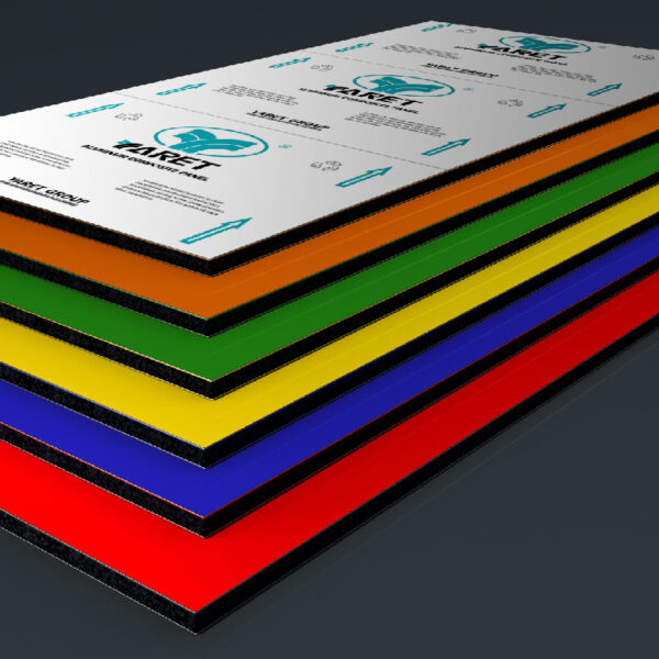
Forward-looking, the better path is physics-first detailing, then parts. New cassette systems decouple stress with sliding anchors, so thermal movement does not print on the face. Pressure-equalized cavities get sized by zone, not rule-of-thumb, to handle peak wind load. Mineral-core MCM, honeycomb, and solid plate each answer a different brief. When you specify, compare stiffness-to-weight and flatness retention, not just thickness. Smart layout tools nest cuts to reduce scrap by 12–18%. That is cost and carbon saved in one pass.
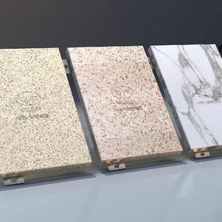
Coatings are not just color. Modern FEVE and PVDF stacks with nano-ceramic primers resist chalking and allow gentle cleaning cycles. Bracket design now targets point thermal bridges with thermal pads and broken rail segments. Digital QA—simple photo checklists tied to grid coordinates—catches out-of-plane drift before the skyline shows it. In short, the principles are clear: isolate movement, ventilate the cavity, and verify the grid. Apply them to aluminum panels of any type, and you’ll get fewer callbacks, tighter energy results, and better acoustics. Different brands and systems, same physics—choose the one that respects it.
How to Choose: Three Metrics That Keep You Honest
Advisory close, with numbers you can track— and no, you do not need a lab to check this. First, movement tolerance: demand documented expansion capacity per panel width and a bracket slip range; verify with a 5 m string-line test across two bays. Second, thermal path: ask for a modeled system U-value with bracket conductivity included, not “center-of-cavity.” If the detail kills 20–30% of your target, fix the rail scheme. Third, cavity performance: specify a minimum 25 mm continuous ventilation gap, pressure breaks at floor lines, and measured airflow at two site points. If the cavity breathes, the wall dries.
Summing up, the product is only half the result. The rest is geometry, airflow, and tolerance control. Set these three checks in your spec, and your façade will act as designed in heat, wind, and time. Keep it direct, keep it measured, and keep it simple. For deeper system references and component options, see yaret.